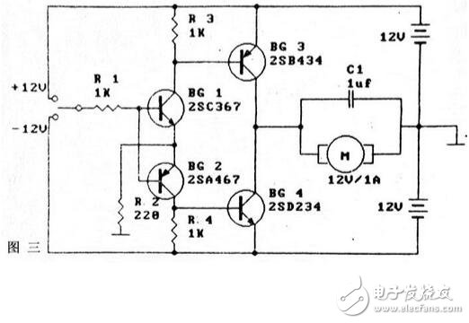
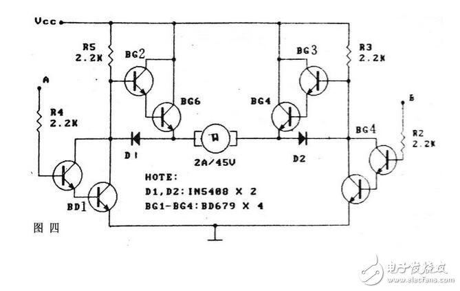
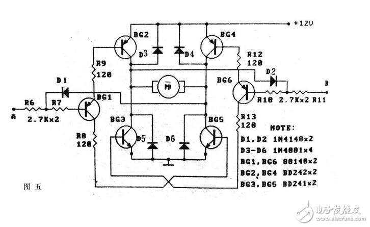
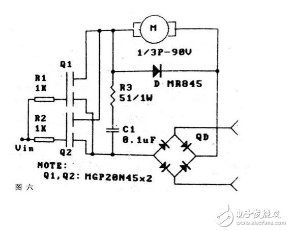
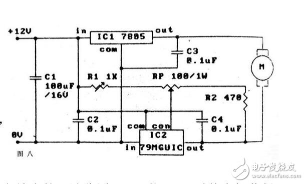
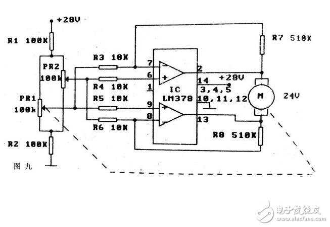
The role of the motor drive circuit: The function of the motor drive circuit refers to the control of the duty cycle by controlling the rotation angle and the running speed of the motor to achieve the method of controlling the idle speed of the motor. Motor drive circuit schematic and circuit control scheme: The motor drive circuit can be driven either by a relay or a power transistor, or by a thyristor or a power MOS FET. In order to adapt to different control requirements (such as motor operating current, voltage, motor speed regulation, DC motor forward and reverse control, etc.), several motor drive circuits are described below to meet the above requirements: The circuit of Figure 1 utilizes a Darlington transistor to amplify the motor drive current. The illustrated circuit extends the 5A of the BG1 to the 30A of the Linton composite tube, and the input can be controlled with a low power logic level. The driving method adopted by the above circuit is a traditional one-arm driving, which can only make the motor run in one direction, and the double-arm bridge push-pull drive can make the control more flexible. Figure 2 shows a single-ended logic input-controlled bridge driver circuit that controls the motor's forward and reverse operation. Another feature of this circuit is that the control supply can be separated from the motor drive supply, so it is well adapted to the motor voltage. Claim. Figure 3 is also a single-ended positive and negative level drive bridge circuit that uses two sets of DC power supplies, which is actually a combination of two inverting one-arm drive circuits. Figure 3 also controls the forward and reverse rotation of the motor. The circuit of Figure 4 drives the motor in reverse rotation based on the Darlington tube. It consists of two parts that are completely symmetrical. When one of the two input terminals A and B is at the é«™ level and the other end is at the low level, the motor rotates forward or reverse; when both input terminals are high or low, the motor stops; if pulse width modulation is used, The speed of the motor can be controlled, so Figure 4 has four combined input states, and the motor can generate five operating states. Here, the addition of the clamp diodes D1 and D2 plays an important role, so that the Darlington tubes BG2 and BG3 are not out of control, which is safer when operated at high power. Another feature of this circuit is that the level of the input control logic is independent of the DC operating voltage of the motor and can be reliably controlled with TTL standard levels. Compared with FIG. 4, the bridge driving circuit of FIG. 5 is more interesting, one of which is to trigger the motor operation with a low level; the second control terminals A and B have a trigger locking function; and the third has multiple protections, such as D1. , D2 trigger lock, D3 - D6 power tube collector protection. Therefore, only three input states are valid for this circuit, and the motor still has five working states. The role of D1 and D2 is: If A is low level, BG1, BG2 and BG5 are turned on, and the é«™ level of BG2 collector will block the input of B terminal through D2 to ensure BG6 is cut off. If this circuit is triggered by TTL circuit, it must be Select the collector open circuit. Because the motor has low requirements for power supply stability, the driving circuit of Figure 6 is an AC power supply scheme. After the AC power is rectified by the full bridge, the MOS field effect transistors Q1, Q2, R3 and C1 used in parallel are driven to filter; The flow diode D is used to prevent damage to the Q1 and Q2 by the high voltage. Figure 7 uses the rectification characteristics of the thyristor to drive the DC motor. This circuit is only suitable for low-power motor speed regulation. The filter network of R2 and C3 can absorb the back electromotive force protection of the motor to protect the SCR, C2 and L filters, which can restrain the power grid. interference. There are many cases where the motor is driven by an integrated circuit, which is different from the direct drive of a general three-terminal regulator. The circuit of Figure 8 enables the motor to obtain a driving voltage from 0V to 7V, thus having low-voltage speed regulation performance, and IC1 is a positive output. Fixed voltage regulator, IC2 is a four-terminal regulator with adjustable negative output. Adjusting R1 can make the motor get zero voltage. Since the heat sink of IC2 is connected to the input end, IC1 and IC2 can use common heat sink to adapt to low voltage. jobs. Figure 9 uses a power-type op amp drive motor, which is a bridge drive circuit. The control signal is obtained from the Wheatstone bridge arm consisting of R1, R2, RP1, and RP2. If RP2 is used for signal detection, the motor feeds back RP1. Tracking adjustment enables error ratio control. The LM378 can provide up to 1A of drive current. This circuit has a wide range of applications in servo systems. KNM1 Series Moulded Case Circuit Breaker
KNM1 series Moulded Case Circuit Breaker is MCCB , How to select good Molded Case Circuit Breaker suppliers? Korlen electric is your first choice. All moulded Case Circuit Breakers pass the CE.CB.SEMKO.SIRIM etc. Certificates.
Moulded Case Circuit Breaker /MCCB can be used to distribute electric power and protect power equipment against overload and short-current, and can change the circuit and start motor infrequently. The application of Moulded Case Circuit Breaker /MCCB is industrial.
KNM1 series Molded Case Circuit Breaker,KNM1 series Small Size Molded Case Circuit Breaker,KNM1 series Electrical Molded Case Circuit Breaker,KNM1 series Automatic Molded Case Circuit Breaker Wenzhou Korlen Electric Appliances Co., Ltd. , https://www.zjthermalrelay.com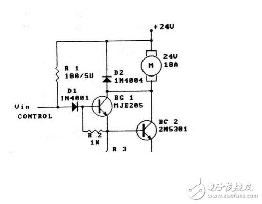


Korlen electric also provide Miniature Circuit Breaker /MCB. Residual Current Circuit Breaker /RCCB. RCBO. Led light and so on .