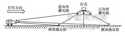
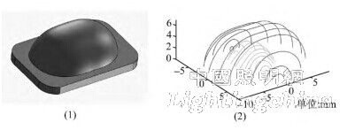
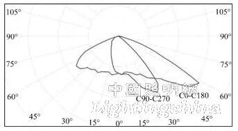
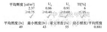
0 Preface As the domestic environmental pollution problem has become increasingly prominent, energy conservation and emission reduction have received unprecedented attention. As the fourth-generation lighting source, LED has the advantages of energy saving, environmental protection and long life. It has been widely used in indoor, outdoor and special lighting. At present, most of the LEDs belong to the (near) Lambertian source. In order to make the LED's illumination distribution conform to practical applications, it is necessary to perform secondary light distribution on the LED. The existing LED light distribution has a reflection type (reflective cup) and a refractive type (lens), and the refractive type light distribution has strong controllability to light, and is widely used in road and tunnel illumination. In order to make LED lighting lamps have higher energy utilization rate, the current light distribution of road lamps is mostly in the form of polarized light. The polarization here means that the light distribution of the luminaire is symmetrically distributed along the direction of travel of the vehicle, and is asymmetrically distributed perpendicular to the direction of travel of the vehicle, as shown in FIG. With the continuous development of road lighting design, the evaluation standard of road light distribution has gradually evolved from the past illumination uniformity to uniform brightness, and uniform illumination is supplemented [1]. The light distribution curve reflects the relationship between the light intensity and the angle of illumination of a certain section of the luminaire. The design of an ideal light distribution curve needs to comprehensively consider the installation height of the lamp, the distance between the pole and the width of the road, so that the parameters of the road illumination quality, such as the road illumination, brightness and threshold increment, are in line with the standard and achieve high efficiency. Healthy and energy efficient lighting purposes. In this paper, a new type of fully polarized lens is proposed, in which the light distribution curve is asymmetrically distributed along and perpendicular to the direction of travel of the vehicle. Such a lens can reduce the effect of the light curtain effect on the driver while obtaining sufficient brightness uniformity. Fig.1 Light distribution curve of traditional polarized lens: Curves C0-C180 and C90-C270 are the light intensity distribution along and perpendicular to the road direction 1 Design of fully polarized LED lens 1. 1 design principle The purpose of the road lighting design is to provide a comfortable lighting environment for the driver and to ensure road traffic safety. In different road environments, there should be a corresponding light distribution design, in which the tunnel is a special road lighting environment. In most tunnels, the vehicle travels in one direction, and the direct light from the upper front luminaire and the reflected light from the lower front ground form the driver's visual effect, as shown in Figure 2. The light distribution design of the tunnel luminaire should ensure that the road surface brightness is sufficiently uniform and minimize the direct illumination of the light to the human eye (reduce the glare). The light emitted by the luminaire can be divided into two categories, forward and backward. The forward propagating light will only produce reflected light, which will form the brightness of the road surface; the small-angle reverse-propagating light will generate reflected light to form the road surface brightness, and the large-angle reverse-propagating light can directly enter the human eye, forming a light curtain and causing glare. The greater the influence of the light curtain, the weaker the ability of the human eye to distinguish objects. Figure 2 Schematic diagram of light propagation from a luminaire The degree of influence of the light curtain is measured by the glare limit threshold increment (TI), and the Urban Road Lighting Design Standard CJJ45-2006 specifies the initial maximum value of TI in the three road types. In road lighting, when the road surface brightness is from 0.05 cm/m2 to 5 cd/m2, the following formula can be used: Where Lv is the equivalent light curtain brightness; Lav is the average brightness of the road surface; n is the total number of lamps in the same row of 500m [2]; K is the age coefficient, generally 10 (23-year-old observer); Eeyei is the ith The illuminance of the luminaire on the retina in the direction of the human eye; θi is the angle between the direction of the light incident on the human eye by the i-th luminaire and the direction of the line of sight of the human eye. The area that the general driver pays attention to is 60 to 160 meters in front of it, and the angle with respect to the horizontal plane is about 1°. Therefore, in the case of a certain height of the pole and the distance between the poles, it is necessary to reduce the light intensity at a large angle of the luminaire to lower the TI value, as shown in Fig. 3. Figure 3 The light intensity distribution of the luminaire at a large angle will cause dazzling effects on the driver. From the perspective of road lighting quality, the main effects of the driver's visual comfort are "zebra pattern" and glare [3]. The “zebra pattern†is mainly caused by the low brightness uniformity (UI value) of the road surface, and the glare is due to the excessive angle of illumination in the longitudinal direction of the lamp (in the direction of the lane). Increasing the longitudinal illumination angle of the luminaire can increase the UI value, but this makes the Eeyei of the glare light too large, increasing the TI value. Therefore, there is a competitive relationship between increasing brightness uniformity and reducing glare value. Unlike traditional tunnel lights with symmetric light distribution along the lane (completely symmetrical or semi-polar), fully asymmetric (fully polarized) light distribution is more flexible. First of all, the completely asymmetric light distribution can make the angle of the light propagating in the reverse direction not too large, and the angle of the light propagating in the forward direction is appropriately enlarged, and the energy is more, so as to ensure that the tunnel road surface has sufficient brightness uniformity. Secondly, in the inspection area between the two lamps, the brightness is caused by the light of the two adjacent lamps. The asymmetric design has a degree of freedom compared to the symmetric light distribution design. . 1. 2 Design method The design idea of ​​the fully polarized LED tunnel light lens is as follows: First, divide the energy hemisphere emitted by the LED light source into several energy units, then divide the target plane into several area units, and finally according to the law of conservation of optical expansion, the law of refraction and the edge optics The principle establishes the energy correspondence between the energy unit and the area unit, and calculates the coordinates of the seed line required to generate the free-form lens model. The seed line is imported into a 3D design software such as Solidworks to generate the desired lens model. This lens design method based on energy meshing has been widely used in LED lighting design [4-6]. The division of the source energy and the target plane is shown in Figure 4. The hemispherical illumination of the LED is represented by the angle (u, v), as shown in Figure 4 (1). The point O is at the center of the LED illumination, and the maximum intensity is along the Z axis. In addition, the size of each energy unit is divided by (Δu, Δv) and corresponds to the area unit (Δx, Δy) on the target plane area, as shown in Fig. 4 (2). The size of each energy unit is: Equation (2) represents dividing the total optical energy Φ of the hemisphere of the LED into M × N parts, and the energy of each part is energy Fig. 4(1) The spatial angle of the LED hemispherical illumination, (2), (3) Correspondence between the energy unit on the LED illuminating sphere and the area unit on the target surface The key coordinate point of the free-form surface lens is calculated by the scientific calculation software Matlab program to convert the above design ideas into mathematical language. Usually, the coordinate points directly come out cannot directly obtain the lens model needed by the road. The main reasons are as follows: . First, the calculation program is to simplify the LED light source into a point source, and then use the law of refraction in optics to solve the free-form surface. However, the actual LED's light-emitting surface is relatively large in size relative to the lens, which may cause errors in the calculation results. In addition, the light intensity distribution of the LED is usually not the ideal Lambertian distribution, that is, the light intensity distribution of the LED is cosine. Secondly, in the calculation process of the seed line, since the calculation of the latter point is the previous point as a reference, the cumulative error of the calculation occurs on the seed line. Finally, road lighting applications need to consider brightness uniformity, while the original calculation method is calculated only by energy (illuminance) uniformity. Therefore, it is necessary to introduce an appropriate grid modulation factor in the program to correct the error [8], and the energy distribution needs to meet the brightness uniformity of road illumination. 1. 3 design examples and results analysis Based on the above algorithm, this example designs a fully polarized LED tunnel light lens for two lanes. The lens used in the lens is Philips' white light Luxeon T, which has a luminous efficiency of up to 130 lm/W. The three-dimensional model of the lens is shown in Figure 5 (1), and Figure 5 (2) is the seed line designed to construct the three-dimensional model. Figure 5 (1) Three-dimensional model of the fully polarized lens, (2) Seed line designed to construct the three-dimensional model Optical simulation of the lens model and the Luxeon T source was performed using optical simulation software such as Tracepro. The material used to set the lens was polycarbonate (PC) and traced using Monte Carlo rays. Figure 6 shows the light distribution curve obtained after 1 million light simulations. The angle of this light distribution curve is about 55° × 130°. In the figure, the C0-C180 curve is the light intensity distribution along the lane direction, and the maximum value is in the vehicle direction; the curve C90-C270 is the light intensity distribution perpendicular to the lane direction. After the IES file is exported by the optical simulation software, the road simulation analysis can be performed using the lighting design software DIALux. The parameters of DIALux are set as follows: The installation height is 5. 5 meters, the pole spacing is 12 meters, the cantilever length is 0 meters, the elevation angle is 15°, the total luminous flux of the lamps is 5000 lm, and the lamps are arranged in a double row relative to the lamps. The asphalt R3 pavement was used for lighting simulation. The simulation results are shown in Figure 7. The simulation results show that the illuminance uniformity UE, the total brightness uniformity Uo, and the brightness longitudinal uniformity UL are 0.88, 0.86, and 0.91, respectively, which are much higher than the national standard requirements of 0.4, 0.4, and 0. 7; The glare limit threshold increment is also better than the national standard requirement 10 [9]. Figure 6. Light distribution curve of the full polarized lens: Curves C0-C180 and C90-C270 are the light intensity distribution along and perpendicular to the road direction, respectively. Figure 7 Road scene simulation results of the full polarized lens model In addition, the simulation results show that the average illuminance Eavg and the average luminance Lavg of the road surface are 49 lx and 2.37 cd/m2, respectively, and the illuminance luminance ratio R[10] can be calculated according to the calculation formula of the illuminance luminance ratio: This R value is within the recommended range (15 to 22lx · m2·cd-1) of the Road Tunnel Ventilation Lighting Design Specification JTJ026. 1-1999 and meets the energy conservation standards. Since the tunnel does not require the ambient illumination coefficient, this parameter is not optimized in this work [11]. 2 Conclusion In this paper, a non-imaging optical theory is used to design a fully polarized LED tunnel light lens based on LED energy grid. Different from the light distribution direction of the traditional luminaire along the road traveling direction, the original light of the LED is considered by considering the requirements of illumination uniformity, brightness uniformity and glare threshold increment in the road lighting design. The strong distribution corresponds to the target surface reasonably, and a lens suitable for tunnel environment application is designed. The lens suppresses the illuminating angle and intensity of the reverse direction of the luminaire to reduce the glare effect on the driver; at the same time, the angle and intensity of the forward propagation direction are increased to achieve the illuminance and brightness uniformity. In the verification of the lighting analysis software DIALux, the illumination effect of UE=0.88, UO=0.86, UL=0.91, TI=6 is achieved. The results show that the fully polarized LED tunnel light lens design is well suited for tunnel lighting applications. Edit: Cedar
HVAC Air Cleaner Purifier, technology with UV Germicidal, Electronic, electrostatic, photocatalyst and photo electronic.
Electronic air cleaners, sometimes referred to as ionizers or electronic air purifiers, use electrically charged filters to reduce the number of airborne contaminants in your home. As air passes through your heating and cooling system, the Electronic Air Cleaner traps large particles (such as dust and dander) in a prefilter. Then, electrically charged filters attract and trap smaller particles (such as bacteria and mold) to prevent them from recirculating through your home.
Electronic Air Cleaner,Hvac Air Purifier,Air Purifier Hvac,Air Duct Cleaner Dongguan V1 Environmental Technology Co., Ltd. , https://www.v1airpurifier.com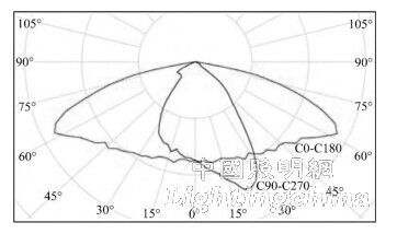


 The division of the energy unit and the target area unit affects the final light distribution effect. The energy partitioning algorithm usually divides the energy hemisphere of the LED into equal parts, and for the target area (such as the lane), the energy distribution is performed by adjusting the size of the area unit (Δx, Δy). If the energy unit is assigned to a smaller area unit (Δx, Δy), the energy density of the area is higher; otherwise, it is smaller, as shown in Figure 4 (3). The polarization design of the LED can be realized by the design method of energy redistribution. The detailed analysis and calculation process can refer to the related literature [7]. This method of dividing the circular illumination of the LED into a rectangular grid conforms to the actual needs of the rectangular road and improves the energy utilization of the luminaire.
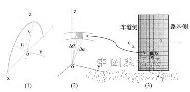

Control: connected with HVAC system.
Install: Return air, Air Duct, Air Handling Unit, Fan Coil.