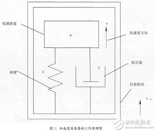
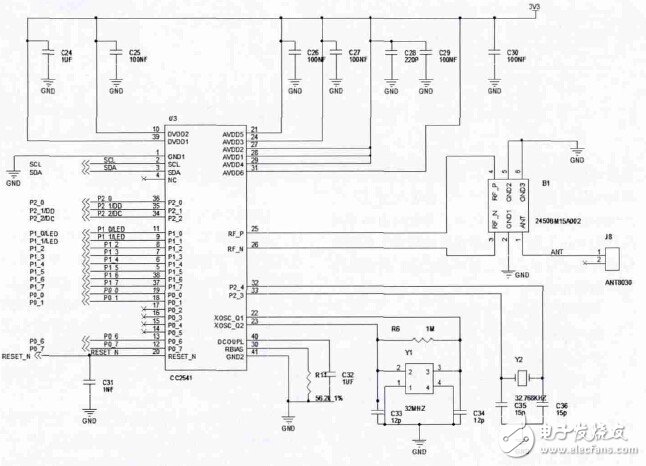
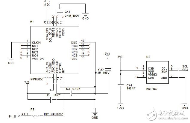
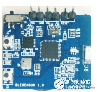
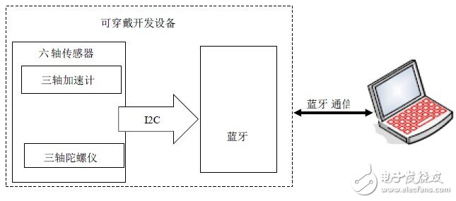
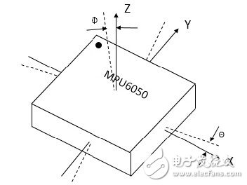
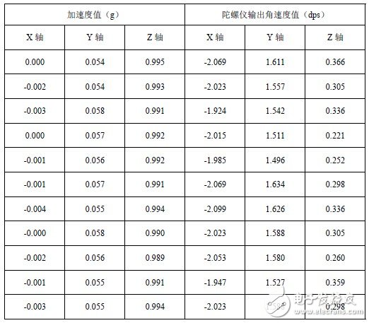
There are more and more wearable devices on the market today, and competition for wearable devices, especially wrist wearable devices, is becoming increasingly fierce. The core of research on wearable devices is the study of wearable sensors. The growing power of wearable devices is related to the increase in the number of wearable sensors used internally and the performance gains. This article is based on MEMS six-axis sensor technology and aims to design a wearable device that can be used for motion track detection. Using the existing Bluetooth 4.0 technology, the data collected by the six-axis sensor is transmitted to the host computer in real time, and the moving trajectory closest to reality is obtained through simulation software such as MATLAB and reasonable data processing. The wearable motion monitoring system is a typical application of wearable computing in the sports field. The wearable motion monitoring system aims to provide users with continuous and accurate motion monitoring without prejudice to user movement. Domestic and foreign scholars have done a lot of work in this research field and developed many related equipment and applications. However, these devices or applications are not sports experts and do not really give accurate advice based on this information. Only general information assessments can be given based on this information. On the other hand, due to the lack of large-scale data processing capabilities, multi-dimensional data analysis capabilities, and in-depth data mining capabilities, even the collected data contains a lot of useful information, even data that can be directly used to analyze motion, based on data. Dealing with mining capabilities will also be overwhelmed by massive data. In view of this, a new wearable system is proposed. The system is based on a MEMS six-axis sensor, which collects the three-axis acceleration and three-axis angular velocity of the six-axis sensor as calibration points generated during the movement of the object, and wirelessly transmits the data to the upper computer equipped with the Bluetooth USBdongle through Bluetooth 4.0 for data processing and Trajectory simulation. The wearable motion monitoring system in this paper is based on the inertial technology of the simulated motion trajectory, and is mainly realized by the motion sensor. The system mainly uses two kinds of motion sensors: three-axis acceleration sensor and three-axis gyroscope sensor. Accelerometers are used to measure the acceleration of moving objects as raw data for calculating speed and displacement. The gyroscope is used to measure the angular velocity of the east object, thereby determining the reference coordinate system of the acceleration sensor of the moving object in the three-dimensional space, which is beneficial to the calculation of the displacement trajectory. 1.1 Acceleration sensor working principle Acceleration is a basic physical quantity that characterizes the nature of an object in space. It can measure the motion state of an object by measuring acceleration. The basic principle of the acceleration sensor can be illustrated by Figure 1, where m is the mass of the square, k is the stiffness of the spring, and c is the damper connected to the instrument case. Figure 1: Working principle of the acceleration sensor The sensor base is fixed to the measured moving body, and thus moves relative to the reference point of the inertial space along with the moving object. Since the proof mass is not fixed to the sensor base, it will be displaced relative to the instrument case under inertial force. The detecting mass senses the acceleration and generates an inertial force proportional to the acceleration, so that the spring generates a telescopic deformation equal to the relative displacement of the mass, and the spring deformation generates a reaction force proportional to the amount of deformation. When the inertial force is balanced with the spring reaction force, the displacement of the proof mass relative to the base is proportional to the acceleration, so the acceleration can be measured by the displacement or inertial force. According to Hooke's law, the formula is as follows: Δx=x0-x (1) F=kΔx=ma (2) Δx is the relative displacement of the proof mass. As can be seen from the above equation, the relative displacement amount Δx of the detected mass is proportional to the acceleration a. 1.2 How the gyroscope works The principle of a gyroscope is that the direction of the axis of rotation of a rotating object does not change without being subjected to external forces. Just like a gyro does not fall when rotating at high speed. However, the actual work of the gyroscope is necessary to give it a force, so that it can rotate quickly, the rotation rate is generally hundreds of thousands of revolutions, so that it can work for a long time. The information of the axis is read in a variety of ways and transmitted to the control system for analysis and processing. 1.3 MEMS six-axis sensor works MEMS inertial sensors use integrated circuit technology and are distinguished from other inertial sensors by their unique processing technology. The advantages are high reliability, low manufacturing cost, and long life. At the same time, it has the characteristics of light weight, easy integration, low power consumption, small size and high-volume production. MEMS sensors amplify signals before they are transmitted on the same chip, increasing signal levels and reducing interference and transmission noise. Especially when performing A/D conversion on the same chip, the signal-to-noise ratio can be improved. The MEMS six-axis sensor is integrated on the same chip by a three-axis gyro sensor and a three-axis accelerometer sensor, which can output the data read by the gyroscope and accelerometer in real time. The principle of the accelerometer is similar to the traditional principle. The working principle of the three-axis gyroscope is different from the traditional gyroscope principle. The traditional gyroscope theory is based on the law of conservation of angular momentum. The object that rotates continuously, his axis of rotation does not change with the rotation of its original bracket. The MEMS gyroscope utilizes the Corio force, the object is driven, and the neck movement is repeated back and forth. The Corio force does not change back and forth in the lateral direction. The main component of this hardware system is composed of the data acquisition of the sensor and the Bluetooth radio. The sensor part is mainly composed of six-axis sensor MPU6050 and air pressure temperature sensor BMP180, and the Bluetooth chip selects TI.  The company's CC2541. The MPU6050 and BMP180 are connected to the CC2541 through the I2C bus to transmit the collected data to the Bluetooth chip. The Bluetooth chip then transmits the collected data through the balun filter and ceramic antenna on the board. Detailed system schematic diagram 2. The two parts of the circuit are integrated on the same circuit board to create a set of wearable development platform, as shown in Figure 3. Through this self-developed development platform, a large number of trajectory experiments can be done, which provides an experimental environment guarantee for the next trajectory simulation. Figure 2 (a): System circuit schematic CC2541 part Figure 2 (b): System circuit schematic sensor section Figure 3: Wearable development equipment Based on the existing wearable development platform, the simulation system performs data acquisition on the acceleration signal generated by the motion trajectory. After pre-processing the acquired signal, the acceleration integral and the later error compensation are completed, and finally a 1:1 simulation of the motion trajectory is realized. The simulation system is mainly divided into three main parts: six-axis sensor, Bluetooth and host computer processing. The six-axis sensor mainly includes a three-axis acceleration sensor and a three-axis gyroscope, respectively collecting the acceleration signal and the angular velocity signal generated during the movement; the Bluetooth is mainly responsible for receiving the data collected by the six-axis sensor, and outputting the data to the Bluetooth signal to the The upper computer; the upper computer handles the main function of data processing. The overall structure of the simulation system is shown in Figure 4. Figure 4: Simulation system structure With the Bluetooth chip, the acquisition rate of the six-axis sensor is defined as 20 sets of data per second, and a set of six values ​​includes three acceleration values ​​and three angular velocity values, each of which includes 16 bytes. The collected raw data is sent directly to the computer for processing via Bluetooth transmission, and then the data is processed and trajectory simulated by MATLAB. As shown in Figure 5, the coordinate system is determined. Figure 5: Schematic diagram of the sensor's coordinate system 4.1 Static state In a completely static state, the wearable development platform is placed on a horizontal desktop, and the Z-axis direction is perpendicular to the horizontal desktop, coincident with the direction of gravity. In theory, the acceleration value is 0 on the X and Y axes, and 1 g on the Z axis; the output of the gyroscope should all be 0. However, due to the presence of random noise, the output value should have a certain deviation. 600 sets of data obtained in 30s were measured. Select 10 of the following tables. The schematic diagram is shown in Table 1. Table 1 4.2 uniform speed Select the X axis of the three axes of XYZ, make a uniform linear motion along the X axis, and collect the data obtained by the sensor. The wearable development platform is moved at a constant speed in the X-axis direction for 19 seconds, and a total of 380 sets of data are collected, and 10 sets of data are selected as Table 2. Table 2 The design of the wearable development platform is based on the basic principle of the MEMS six-axis sensor MPU6050, and combined with the Bluetooth transmission technology, the data collected by the motion can be quickly and easily transmitted to the PC. The collected data is mainly used in the research of late wearable computing. Solar Batteries And Panels,Solar Batteries 1000Ah 36V,Solar Energy Storage Lamp Battery,Rechargeable Lithium Solar Battery Shaoxing Honyo International Trading Co., Ltd , https://www.honyopower.com 1 Basic principles of wearable motion monitoring system

2 Design of wearable hardware system
3 motion trajectory simulation system design
4 motion trajectory simulation test results

5 Conclusion
Design of wearable motion monitoring system based on MEMS six-axis sensor
1 time
Window._bd_share_config = { "common": { "bdSnsKey": {}, "bdText": "", "bdMini": "2", "bdMiniList": false, "bdPic": "", "bdStyle": " 0", "bdSize": "24" }, "share": {}, "image": { "viewList": ["qzone", "tsina", "tqq", "renren", "weixin"], "viewText": "Share to:", "viewSize": "16" }, "selectShare": { "bdContainerClass": null, "bdSelectMiniList": ["qzone", "tsina", "tqq", "renren" , "weixin"] } }; with (document) 0[(getElementsByTagName('head')[0] || body).appendChild(createElement('script')).src = 'http://bdimg.share. Baidu.com/static/api/js/share.js?v=89860593.js?cdnversion=' + ~(-new Date() / 36e5)];