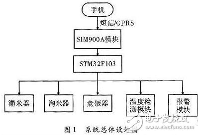
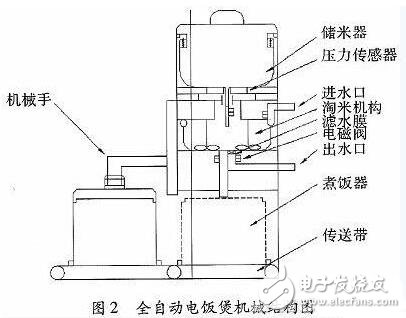
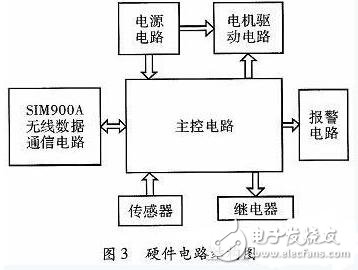
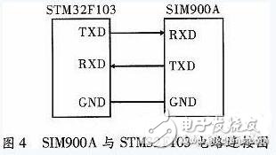
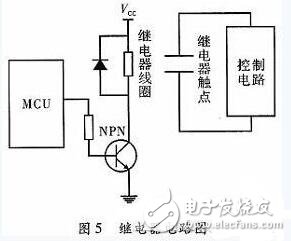
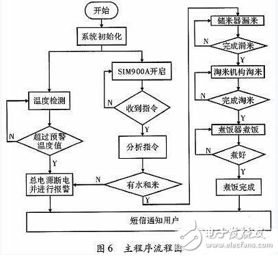
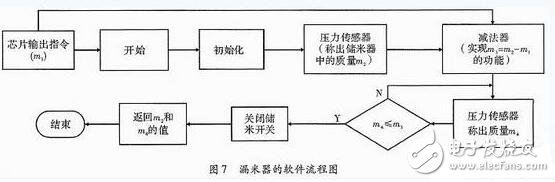
Nowadays, the rice cooker is developing in the direction of integrating cooking, soup and heat preservation. Although the current rice cooker has the function of making an appointment for cooking, but the appointment time is too long and affects the taste of rice, the automatic rice cooker designed in this paper is embedded and embedded. Technology and wireless communication technology not only realize remote intelligent control of rice cooking, but also ensure a good taste of cooking. 1 How does the automatic rice cooker work? The designed rice cooker is in standby mode when it is not working. When the SIM900A module receives the SMS or GPRS control command sent by the user's mobile phone, it sends the command to the STM32F103 MCU, and the MCU analyzes the command, and then controls the rice cooker to automatically leak rice and pan. The whole process of rice and rice cooking, and the temperature sensor is used to detect the working temperature of the rice cooker in real time. At the same time, it can intelligently alarm according to the working state of the rice cooker to ensure the reliable and stable operation of the rice cooker. The overall design of the system is shown in Figure 1. 2 Mechanical structure design This system is a new mechanical structure improvement for ordinary rice cookers, and is designed from three aspects: rice storage device, rice cooking mechanism and rice cooker, as shown in Figure 2. The top of the device is a rice storage device that can store up to 5 kg of rice at a time. The pressure sensor can accurately measure the amount of rice required for cooking, the solenoid valve controls the in and out of the rice and the water, and the rice-washing mechanism performs the rice-washing operation under the driving of the stepping motor. After the panning, the rice and the right amount are The water is sent to the rice cooker, and then the rice cooker is transported from the idle position to the designated working position by the conveyor belt for cooking, and the robot automatically places the rice cooker lid on the rice cooker under the driving of the motor, and the device is placed on the microwave oven. Automatically controlled under control. 3 hardware circuit design The hardware circuit of the device is composed of main control circuit, SIM900A wireless communication circuit, sensor circuit, relay circuit, motor drive circuit, power supply circuit, alarm circuit, etc. The hardware circuit is shown in Figure 3. The main control circuit chip should have high performance, low cost, low power consumption and fast storage speed. This circuit uses ARM core 32-bit single-chip STM32F103 as the control core. It has a wide operating temperature range, 7 timers and 9 communication interfaces. It has 7-channel DMA controller and 2 12-bit A/D modules. Number converter. The working frequency band of SIM900A wireless data communication circuit is EGSM900 and DSC1800, and the working temperature range is -30~+80°C. It has power saving, fast transmission rate, support packet broadcast control channel, support real-time clock, and support software to control RTS/CTS hardware. Flow control and other characteristics. The SIM900A in this design is used to receive the short message or GPRS control command sent by the mobile phone, and then transmit the command to the STM32F103 chip, thereby realizing the remote control of the rice cooker. The connection between the SIM900A and the controller is shown in FIG. 4 . The relay is mainly used to control the opening and closing of the solenoid valve and the shutdown of the main power supply of the rice cooker. The working principle is shown in Figure 5. 4 software design 4.1 main program software The software control flow of the system is: After receiving the external SMS or CPRS command, the SIM900A wireless communication module sends the command to the STM32F103 main control chip, then starts the rice cooker system and monitors the working temperature in real time, and the system intelligently alarms according to the working state, and the STM32F103 controls the rice cooker. Realize automatic leakage, rice, cooking and other functions, the main program flow is shown in Figure 6. 4.2 Software design of the rice leakage device STM32F103 receives the command issued by SIM900A wireless communication module: If the number of meters required for n people to eat is m1; at this time, the program of the rice eliminator is started and initialized, and the meter quantity of the initialized rice storage device is measured as m2; then the data is sent to the control. The core calculates the difference m3=m2-m1, and then causes the rice eliminator to continue to leak rice and detects the weight m4 of the rice in the rice storage device through the pressure sensor. When m3=m4, the rice storage switch is turned off and the subroutine is returned. In the m2 and m4 values, and ending the program, the flow of the missing rice device is shown in Figure 7. Optical Cable Cross Connection Cabinet
Modular design of Optical Cable Cross Connection Cabinet(FDH,FOCC) provides the largest flexibility; satisfy the needs of the present and future development. The body using the stainless steel and surface using electrostatic spray so it has good corrosion resistance and anti-aging function, the wind protection class of the body achieves the IP66 level. The effect of defense dewing is excellent. The module tray can spin out of 90 degrees around the axis in the left front, and the bevel of the adapters within the module takes on 30 degrees. The clip-locked installation ensures the bending radius of the fiber directly and prevents the eyes from injury. Weld disk can spin out of 90 degrees, and then draw out, so it is convenient to construction, and also convenient to expansion and maintenance. Have doors in the front and back, have ample space for cabling, convenient to operation and maintenance. Have reliable device for fastness, peeling and grounding of the optical cables. Insulation resistance between high voltage protection earth and box20,000MΩ /500V (DC)
Communication Optical Cable Cross Connection Cabinet is interface equipment to contact trunk optical cable and wiring cable. It is compose of box, inside structure, optical fiber connector and some accessories. The function is to connect, store, dispatch and enlarge optical fiber. The material of box is cold-roll steel sheets, SMC fiber strengthen unsaturated polyester or stainless steel material. It has high resist destroy capacity, high strength, safety and stability. It has the device to bring optical cable, fix and protect. It has optical fiber termination device which could easy to splice, fix and maintain the optical cable fiber and optical cable fiber/optical fiber pigtail. At the same time, it has more space to store the surplus optical cable and fiber. Through the optical fiber connector, it could dispatch the fiber serial number of optical cable and change the transmission system route rapidly and expediently.
Cross Connection Cabinet, Optical Cable Cross Connection Cabinet, FDH, FOCC NINGBO YULIANG TELECOM MUNICATIONS EQUIPMENT CO.,LTD. , https://www.yltelecom.com