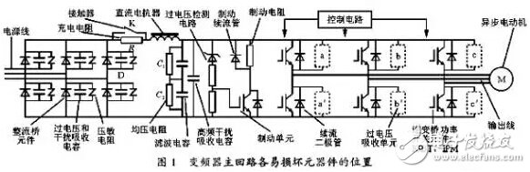
The damage of the inverter inverter module is mostly caused by the damage of the drive circuit, causing the two switching devices on one bridge arm to be turned on at the same time. Inverter inverter power module damage is a common fault in other frequency conversion equipment such as vector inverters and energy-saving inverters. To solve this problem, only the root cause of damage can be found, and the possibility of damage again can be eliminated first. Change the module, otherwise the new module will be damaged again. First, judge The inverter power module mainly has IGBT, IPM, etc., check whether the appearance has exploded, and whether the terminal and the connected printed board have ablation marks. Use a multimeter to check whether CE, GC, and GE are connected, or use a multimeter to measure whether P, U, V, W, and N have inconsistencies in U, V, and W resistances, and the control poles of each driving power device are U, V, W, Whether the resistances of P and N are inconsistent, to determine which power device is damaged. Second, the cause of damage (1) The quality of the device itself is not good. (2) The external load has severe overcurrent and unbalance. The winding of one phase of the motor is short-circuited to the ground. There is a phase short circuit internal short circuit, the load is mechanically stuck, the phase is broken, and the output wire is short-circuited or short-circuited to the ground. (3) The capacitor is connected to the load, or the capacitor is too large due to improper wiring, so that the power tube has an inrush current. (4) The user's grid voltage is too high, or there is a strong transient overvoltage, causing overvoltage damage. (5) The overvoltage absorbing circuit of the power switch tube inside the machine is damaged, causing the IGBT to be damaged due to the inability to effectively absorb the overvoltage, as shown in the figure below. (6) The filter capacitor is aging due to age, the capacity is reduced or the internal inductance is increased, and the overvoltage absorption capability of the busbar is reduced, causing the overvoltage on the busbar to be too high and damaging the IGBT. In the normal operation, the overvoltage on the busbar is converted from the inductive energy storage of the busbar circuit when the inverter switching device is turned off. (7) The front-end opto-isolated devices of IGBT or IPM power devices are broken down due to breakdown, or the ignition and breakdown of dust and moisture in the printed circuit board isolation device cause damage to IGBT and IPM. (8) Inappropriate operation, or defective in the product design software, causing the simultaneous switching of the upper and lower power switching devices at the same time in the unstable situation such as interference and power-on and shutdown. (9) Lightning strikes, intrusion of houses, intrusion of foreign objects, accidental contact by inspectors, etc. (10) The filter capacitor has been replaced by maintenance. Because the quality of the capacitor is not good, or the line connecting the capacitor is longer than the original, the inductance is increased, resulting in a significant increase in the overvoltage of the bus. (11) The front-stage rectifier bridge is damaged, and the IGBT and IPM are damaged due to the AC power entering the front stage of the main power supply. (12) Repair and replacement of the power module, because there is no static protection measures, the IGBT is damaged during the welding operation. Or due to poor handling, such as heat dissipation, fastening, and insulation during repair, it may cause damage due to short-term use. (13) The IGBT is used in parallel, and the consistency of the model and batch number is not considered in the replacement, resulting in uneven current and damage of the parallel components. (14) A component of the internal protection circuit (overvoltage, overcurrent protection) of the inverter is damaged and loses its protection function. (15) A certain group of power supplies inside the inverter, especially the IGBT driver stage +, - power supply is damaged, the output value is changed or the insulation between the two groups of power supplies is broken. Third, replace The inverter module can only be replaced if the root cause of the damage is detected and the possibility of damage is removed first, otherwise the new module replaced will be damaged. (1) IGBTs should be protected from electrostatic damage as well as insulated gate field effect transistors. The fundamental measure to prevent damage in assembly welding is to connect all the machines to be repaired, IGBT modules, soldering irons, people, operating table pads, etc., so that the operation is performed at the same electric field potential, and all connections are common. It is better if it can be grounded. In particular, the electric iron head can not be equipped with high-potential power supply, and the oscilloscope power supply should be isolated by a well-isolated transformer. The IGBT module must keep the control electrode G and the emitter E connected before it is used. Do not remove the anti-static protection GE connection measures before leaving the factory. (2) Apply thermal grease between the power module and the heat sink to ensure that the thickness of the coating is 0.1 0.25mm, the contact surface is more than 80%, and the tightening torque is applied according to the size of the fastening screw (M4 13kg?cm, M5 17kg?cm, M6 22kg) ?cm) to ensure that the module is well cooled. (3) When the machine is disassembled, take notes on the parts to be removed, the thread ends, and the parts. The various technical measures on the original assembly shall be handled during reassembly and shall not be simplified or omitted. For example, the input twisted pair, the resistance value of each electrode connection, the insulation, the absorption plate or the absorption capacitance should be maintained as they are; the cleaning of the soldered printed circuit board should be cleaned and the painting of the creepage prevention should be prevented. And to ensure reliable insulation, not to wear less and misplaced parts. (4) Parallel modules require the same model number and number. When the numbers cannot be consistent, ensure that all modules connected in parallel have the same performance. (5) For the copper parts that are caused by the bomber, the burrs should be rounded to avoid damage caused by over-voltage discharge. Fourth, the power after the replacement of the module After the module is replaced frequently, it is burned and burned. In order to prevent such accidents, a resistor is generally connected in the DC main circuit of the inverter. The resistance is 1 y 2 赘 and the power is 50 W or more. Due to the current limiting action of the resistor, the module will not be damaged even if the fault is turned on. When the current is idling, the current flowing through the resistor is small, and the voltage drop is also small, and the no-load inspection can be performed. Generally, as long as the no-load operation is normal, the removal of the resistor will be normal. The Wireless Car Charger is a phone holder and a
charger at the same time! And the charger is not only for in your car,
but also very functional for at your office or your room, so you can
enjoy charge wireless at multiple places!We are a professional Chinese manufacturer of Wireless Car Charger , and look forward to your cooperation!
Best Wireless Car Charger,Car Holder Wireless Charger,Magnetic Wireless Car Charger Manufacturer in China Reteck Electronic Co., Ltd. , https://www.reteck.com