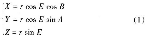
GPS can provide continuous, high-precision, real-time time reference, three-dimensional position, three-dimensional speed, full-circumference ambiguity and other data, with good performance and high precision, so it is widely used in GPS carrier phase attitude measurement, precision guidance, SINS / Military and civilian fields such as GPS integrated navigation and embedded vehicle navigation monitoring. Embedded systems, in their low power consumption, small size, high stability and portability, occupy an important position in GPS applications. This paper studies the acquisition and processing of GPS positioning information of a military vehicle based on embedded microprocessor S3C2440 and WindowsCE 5.0 (WindowsCE) based on ARM920T core. This article refers to the address: http:// 1 System hardware/software platform overview The hardware platform structure of the vehicle GPS positioning information acquisition system is shown in Figure 1. 2 Positioning information data format The output data of GPS follows the NMEA-0183 protocol standard, which is the US Navy's electronic equipment standard. According to the NMEA-0183 protocol, to obtain GPS positioning information, the baud rate of the serial port must be set to 4800b/s, the data bit is set to 8 bit, the stop bit is set to 1 bit, and the check is set to none. The protocol defines standard information for GPS receiver output. The most common and most widely used statement formats are: $GPRMC, $GPGGA, $GPGSV, $GPGSA, $GPGLL, and more. The GPS data formats applied to it include $GPRMC, $GPGGA, and $GPGSV. Among them, use the $GPRMC statement to obtain time, latitude, longitude, speed, year, month and day information, use the $GPGSV statement to obtain altitude information, use the $GPGSV statement to obtain visible satellite number information and satellite azimuth and elevation information for satellite acquisition. view. For the meaning of the data segment of each statement, refer to the NMEA-0183 protocol standard. 3 Software implementation of GPS positioning information acquisition and processing The software development of this system is realized by MFC programming technology in the visual development tool Embedded Visual C++ (EVC). The concept of a buffer is used in data processing. It accumulates the XOR of the received data while sending the corresponding data field into the buffer. This not only reduces the complexity of data extraction verification, but also improves the continuity and correctness of data processing. When the GPS data body status is completed, when the "*" character is entered, the data check status will be entered, which is used to judge whether the data reception and processing are valid or not. If the verification is successful, the reception is valid, and after receiving the CR and LF characters, it will jump to the start state again. If the verification fails, the processed data is discarded and jumps directly to the start state. In Figure 4, m_strRecDisp is a CString variable that represents the string that receives the data. In the program flow, the two most important functions are: character (string) lookup function and string interception function. Obviously, if the distance between the satellite P and the observation point is r, E is the elevation angle of any visible satellite P, and B is the azimuth of the satellite, then the three-dimensional coordinates of P are (X, Y, Z) satisfy: 4 Experimental data and analysis After setting the serial port parameters, open the serial port COMl to obtain experimental data. Figure 7 shows the measured data on a certain type of military vehicle. The measured data interface was taken at 9:45 pm on November 10, 2009 at a training ground. The data is measured at rest. The data displayed by the positioning includes "raw data" and information such as "latitude and longitude, time, altitude" after parsing. By analyzing the data in the interface of Figure 7(a), it is found that there are two $GPGSV statements, and the number of satellites used for positioning in the Edit box corresponding to "Stars" is 8, since each GPGSV can display up to 4 satellites. Information, so the $GPGSV statement is two. This shows that the number of stars is consistent with the number of $GPGSV statements. To obtain valid GPS positioning information, at least 4 positioning satellites are required. This also shows that this data is valid positioning data. The latitude and longitude information displayed by the interface is N: 38°3.6788', E: 114°29.1765'; wherein N represents north latitude and E represents east longitude. Using GoolgeEarth software to view the data, the precise longitude/latitude information of the south gate of Shijiazhuang Ordnance Academy is: 38°3.1650' north latitude and 114°29.0046' east longitude. The precise longitude/latitude information of the west gate of Ordnance Academy is: North latitude 38 °3.394O', east longitude 114°28.5432'. By comparing with the latitude and longitude information of the two, it is found that the accuracy and latitude information of the real-time display of the interface is very accurate. By comparing the standard Beijing time in real time, the time and date information display is also completely correct. 5 Conclusion GPS positioning is a single point positioning, using a receiver to observe the satellite, and independently determine the absolute position of the observation point in WGS-84 (geocentric coordinates). The system uses ARM9 as the embedded microprocessor and WindowsCE as the embedded operating system. The communication between the GPS receiver and ARM is realized through the serial port, and the GPS positioning information acquisition system of a military vehicle is constructed. Experiments show that the system can display GPS positioning data with high precision and long-lasting efficiency in real time, which has important practical value and reference significance. Easy Electronic Technology Co.,Ltd , https://www.nbpcelectronicgroup.com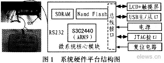
The platform can be divided into 3 major modules:
1) The micro system core module consists of ARM920T-based 32-bit embedded microprocessor S3C2440, SDRAM and Nand Flash and bus interface. Two 32 MB HY57V561620 form a 64 MB SDRAM memory for running the system main program. The Nand FlashK9F1208UOM with a storage capacity of 64 M×8 bit has a dot-point protection function for storing the operating system kernel, bootloader startup code, and user program.
2) The GPS raw data receiving module consists of a GPS receiver and a PS antenna that conform to the NMEA-0183 protocol standard. Through the external GPS receiver, the received GPS original information is sent to the embedded microprocessor for data analysis, and finally the information such as the position, speed and altitude of the location of the vehicle is obtained.
3) Peripheral control module includes LCD+ touch screen, USB master/slave port, power supply, JTAG debug interface, reset circuit. Donghua's own 4-wire analog resistive touch screen and hardware-driven 3.5# TFT LCD are used for human-computer interaction and GPS information after real-time analysis. The USB main port is used to expand the U disk for data storage. The slave port is used to download the WinCE kernel file and interact with the software development host. The JTAG debug interface is used for hardware debugging and burning the bootloader.
The software platform is Microsoft's embedded operating system WindowsCE, which is user-friendly, supports nested interrupts, better thread response, more priority levels, supports serial port and network communication, has rich API functions, and has powerful development tools. Multi-hardware platform support, support for ARM, MIPS and other processors. The Windows CE operating system that has been customized by Platform Builder is shown in Figure 2. 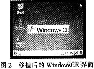
3.1 GPS data processing state conversion GPS and ARM use RS232 serial port to communicate, serial port object is responsible for receiving data, and put the received data into the serial port buffer. The GPS object is responsible for processing the data received by the serial port object according to the protocol structure. Figure 3 is a schematic diagram of state transition between GPS data processing. The GPS data processing state includes a total of four states: a start state, a data frame header state, a GPS data body state, and a check state. 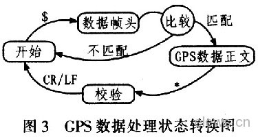
The start state is the start state of a data frame that processes and determines the start character $ of the data frame. If the start symbol is not the $, the data frame head state is used to determine whether the format of the data frame matches the target data frame we currently need. If they match, they will be returned to the next state: GPS data body status, starting data processing. If it does not match, it will move to the start state.
3.2 Interception of Complete GPS Data Frames Understanding the mutual conversion between the four states of GPS data processing, the following discusses the extraction and processing of a complete GPS data frame, which is the key to obtaining GPS GPS positioning data. The extraction process of a complete GPS data frame is shown in Figure 4. 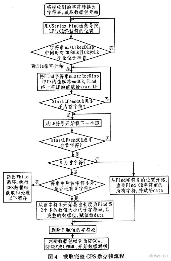
1) Character (string) lookup function The function CString::Find() is used to find a single character or a substring that first matches the target character (string) from an existing string. An important function prototype is: int Find(TCHAR ch, int nStart)const: where ch is the target character to find, and nStart is the starting position.
2) String interception function The function CString::Mid() is used to intercept a character. It can also intercept a substring from a specific position. The return value is a character or a string constant. The function prototype is: Mid(int nFirst, intCount) const; where nFirst is the position where the string begins to be intercepted, and nCount is the number of intercepted characters.
3.3 Processing of GPS data frame After extracting a complete data frame, assign the data frame to the CString variable data, and then send the character content to the buffer pBuffer continuously. After decompressing the data frame, enter the figure. The GPS data frame processing flow shown in 5. When processing GPS time data, because Beijing is located in Dongba District, the UTC time is 8 hours away from Beijing time. After UTC time, if you want to get the standard Beijing time, you should add 8 hours based on this time. 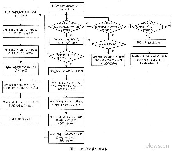
3.4 Acquisition of 2D satellite view The acquisition of the satellite view first uses the station-centered plane coordinate system. The coordinate system is shown in Figure 6. The center plane of the station is the Z axis and the normal is normal, and the X axis is perpendicular to the Z axis and points to the north pole. The Y axis is perpendicular to the Z axis and is positive eastward. 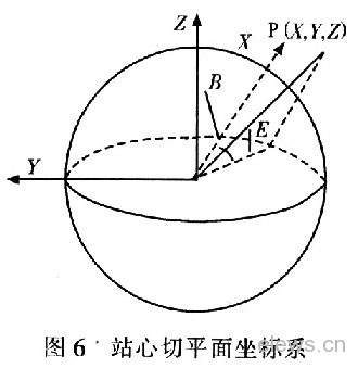
Because the two-dimensional graphics are drawn, the hemispherical coordinate system can only be compressed into the plane of the observer (referred to as the base surface). The position of the satellite represented on the map is actually the projection point of the satellite on the plane. There are two parameters of the coordinate system, one is the azimuth of the projection point of the satellite and the observer's azimuth relationship; the other is the elevation angle that expresses the true position of the satellite based on the base surface and the elevation angle of the observer. . With these two parameters, you can uniquely identify a point of physical significance in the coordinate system. In the design of this system, the design is simple coordinate system, which consists of 2 concentric circles and 4 straight lines. The idea of ​​a simple coordinate transformation algorithm before drawing the satellite view is to convert the actual azimuth and elevation coordinate of the satellite into the horizontal and vertical (PX, PY) coordinates in the plane, as shown in equation (2). Among them, (POX, POY) are the pixel coordinates of the two concentric circle origins (considered as observation points) on the LCD, and T is 1/4 of the length of the dialog window client area. 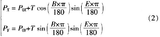
3.5 Implementation of Serial Port Reception To complete the collection of GPS positioning information, the main API functions of the serial port that need to be implemented include:
1) Open the serial port function. The prototype is Open (LPT OpenPort (LPCTSTRPort, int BaudRate, int DataBits, int StopBits, int Parity). Among them, Port represents the serial port name, such as COMl, BaudRate is the baud rate, DataBits is the data bit; StopBits is the stop bit, Parity For parity.
2) Turn off the serial port function. This function is used when an error occurs in the program operation serial port to close the serial port. The main method of implementation is: first determine whether the value of the serial operation handle hComm is INVALID_HANDLE_VALUE, if so, call SetCommMask(), change the EV_RXCHAR in the above code segment to 0, then clear the buffer, and then close the serial by using the CloseHandle function. Port operation handle.
3) Add open serial port click event code, which is realized by creating a serial port receiving thread and display thread.
4) The serial port receives the thread CommRecvTread() and the callback function OnCommRecv(). The serial port receiving thread is an infinite loop, which continuously queries the serial port receiving thread to exit the event m_Exit-ThreadEvent. If the exit event is valid, the loop ends with an exit. If the read serial port function query is used to know that the data is received, the serial port receives the successful callback function 0nCommRecv(). 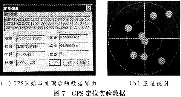
The speed information is measured at rest, so the ideal speed is 0 k/s. The actual measured data is 0.060 00 k / s, as discussed above, the speed information converted from 1 k / s into standard is about 0.514 444 m / s, so the measured speed error is about O. 030 867 m/s. It can be seen that the measured velocity error is relatively small.
The altitude information displayed on the interface is: 68.800 00 m. According to the information provided by the Planning Bureau of Shijiazhuang City, the terrain in the second ring road of Shijiazhuang City is high in the northwest, with an altitude of 81.5 m, a low southeast and an altitude of 64.3 m. There is still a slight error in the measured altitude. This may be related to the drift of the received GPS signal. It can be seen from the satellite view in part (b) of Figure 7 that the azimuth relationship between the satellite and the observation point can be clearly expressed, and the satellite number can also be displayed in real time, from top to bottom: 23, 17, 3, 4 , 19, 20, 32, 11.